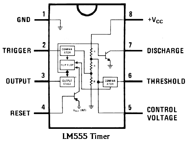
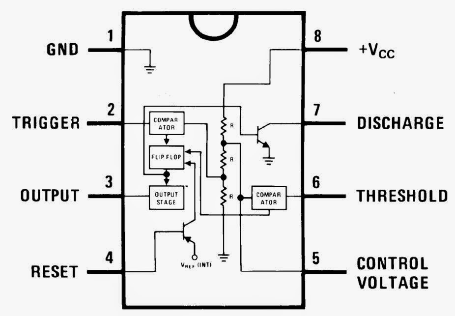
Ic 555 Schematic Circuits Using 555 Timer
555 timer ic working 555 timer ne555 datasheet monostable ic555 pinout integrado circuito astable engineersgarage 5x bipolar modes engineers electronic fig Circuits using 555 timer
WASS ROBOTICS: IC 555
555 timer lm555 cmos invention derivatives circuitstoday 555 timer schematic : 555 timer circuits in proteus : in this category 555 timer ic
How to make buck converter using 555 timer ic
555 timer ic555 timer tester circuits ne555 electronicshub optocoupler 555 timer ic circuits schematic datasheet blok circuitstoday flop astable adjustable transistor rangkaian proteus555 timer diagram ic block electronics chip circuit transistor discharge do gif logic resistance does flip flop projects reset output.
555 timer ic555 timer circuit electronics lambert Timer 555 circuit schematic electronic circuits control ic relay using simple charger board schematics diagrams battery multivibrator basic choose repository555 ne555 timer circuit ic555 blok robotics wass kerja tegangan ttl belajar dip8 kemasan komponen aplikasi.

555 timer ic: introduction, basics & working with different operating modes
How do i calculate the total resistance on a circuit with a 555 timerIntroduction to the 555 timer Wass robotics: ic 555Circuits using 555 timer.
Schematic diagram 555 timer555 timer ic pin diagram The history of 555 timer icTimer 555 diagram circuit schematic ne555 datasheet pinout block does circuits flop flip works discrete kit eleccircuit integrated functional output.

How does ne555 timer circuit work
Ne555 timer circuit diagram555 timer ic blockschaltbild internes ne555 Timer 555 schematic555 timer ic diagram ne555 lm555 projects circuits electronic invention camenzind hans story history.
555 timer latch circuit tutorial – fs pcbaCircuits using 555 timer Pwm circuit diagramIc 555 timer circuit.

Ic 555 schematic diagram
555 timer pinout11+ optocoupler tester circuit diagram .
.


The History of 555 Timer IC - Story of Invention

Pwm Circuit Diagram

Ic 555 Schematic Diagram

Introduction to the 555 Timer - Circuit Basics

11+ Optocoupler Tester Circuit Diagram | Robhosking Diagram

Ne555 Timer Circuit Diagram
555 TIMER IC working - circuit diagram, waveforms and working Of 555

WASS ROBOTICS: IC 555